Writing a Debugger From Scratch - DbgRs Part 7 - Disassembly
(New to this series? Consider starting from part 1)
At the end of the last post, DbgRs could display stacks, which is the single most powerful tool in the debugging arsenal. But once you have those frames to examine, you need to understand what that code was doing. Source code is one place to look at, but if you’re using a low level debugger like WinDbg or KD there’s a good chance you need to see the assembly code, which means we need a disassembler.
The code for this post is in the part7 branch on github. You can also view the changes from part6. If you see any mistakes or ways to improve the code, feel free to create issues on the GitHub repo or submit a PR. The initial version of the code for this part came from expend20, who contributed the integration of DbgRs with iced-x86!
This article will be a little different than some of the others, because I want to talk about the challenges of disassembling code, but writing a full disassembler could be an entire series to itself. So while this post will dive into some of the details (sometimes too deep) of how to disassemble x86, it won’t be sufficient depth or breadth to cover the topic. So for the sake of making a functional debugger, DbgRs will be using a rust crate for disassembly rather than one written from scratch.
As usual, this will be specific to Windows x64 code. If you are completely unfamiliar with x64 assembly code, you may want to read the faker’s guide to assembly first.
Note that the definitive guide for Intel CPUs is the Intel SDM. That said, I find ref.x86asm.net and wiki.osdev.org to have some helpful tables and descriptions of instruction encoding, and I’ll be linking to relevant parts of those pages.
The “C” stands for Complex
The x86 architecture is a CISC (Complex instruction set computer) architecture. There are age-old arguments fighting about RISC vs CISC, and I won’t revisit those here, except to say that one big disadvantage of writing a debugger for a CISC architecture is that the instruction encoding is… complex. For x64, that means that instructions are a variable length, taking anywhere from 1 to 15 bytes. It also means that a set of opcode prefixes can subtly alter the behavior of an instruction, or change an instruction to another operation altogether. And the memory addressing modes are complex as well, the behavior of which can be surprising (and has been influenced by the long evolution from ancient x86 processors).
Backwards compatibility with older instruction sets is a major reason why the instruction set continues to be complex. Many of the instruction encodings that are still used today originated from the earliest processor designs. Here’s the description of the PUSH instruction encoding from the 1978 Intel manual for the 8086 processor.
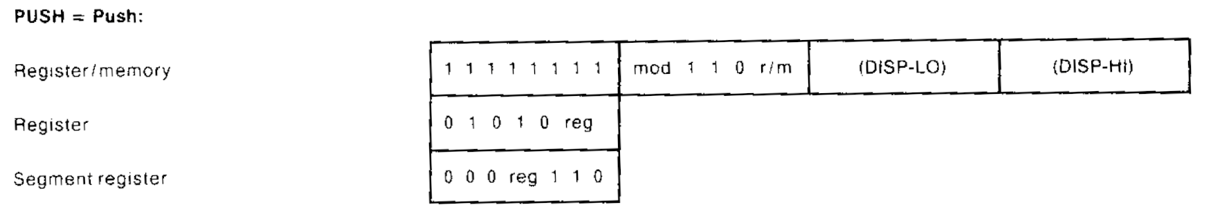
There are three different forms of the PUSH instruction here. All three of them still exist today, 46 years later! These encodings have survived the transition from a 16-bit architecture to a 32-bit architecture, and then again from a 32-bit architecture to a 64-bit architecture!
This transition from 32-bit code to 64-bit code was seen as an “opportunity” to break compatibility with the legacy instruction set, which was often blamed (sometimes unfairly) for the inadequacies of the processor family. Ultimately, however, the instruction set that won was created by AMD and was called AMD64, and it largely built on the existing 32-bit code by extending it with something that almost looked like a superset of the existing instruction set. Both instruction sets are available in all modern x86 processors, which leads to another important point about disassembling code. Instruction decoding is dependent on the context of the instruction, including the address it’s being decoded at (important for relative addressing modes) and the attributes of the code segment being executed, such as default address size, default operand size, and whether the code segment is for 32-bit or 64-bit code. Before we get into that, though, we should start with the anatomy of an x86 instruction.
Parts of an instruction
| Instruction Prefixes | Opcode | ModR/M | SIB | Displacement | Immediate |
|---|---|---|---|---|---|
| 1 byte each | 1-3 bytes | 0 or 1 byte | 0 or 1 byte | 0, 1, 2, or 4 bytes | 0, 1, 2, or 4 bytes |
An x86 instruction can be broken up into 6 distinct parts. All parts are optional except the opcode.
The opcode determines the operation to be performed, and while Intel describes it as 1-3 bytes, there are cases where the opcode “leaks” into the other parts of the instruction, such as “mandatory prefixes” that change the interpretation of the opcode, and the ModR/M byte where 3 of the bits (the reg/opcode field) are an extension of the opcode field. The prefix bytes typically modify the operation in some specific way. The remaining bytes in the ModR/M, SIB, displacement, and immediate fields all describe the operands. We’ll start at the beginning by looking at the prefixes.
Prefixes
Each x86 instruction can start with an arbitrary number of prefixes. Prefixes can typically come in any order or be duplicated, and are often allowed by the processor even when nonsensical (although these cases sometimes confuse disassemblers, and by extension, emulators).
The LOCK prefix (F0) can be used to perform atomic operations (with respect to other cores in the same system) such as an atomic read-modify-write. If two cores on the same machine are running a INC [mem] on the same memory address, it’s possible to “lose” an increment if they each read the same value before one of them has a chance to write the incremented data back. With a LOCK, that operation becomes atomic (potentially with large performance costs). The LOCK prefix is unique in that it is applicable to a small number of operations, and using it on any other operation (or a non-memory operation) results in an invalid instruction exception.
Then we have the “segment override” prefixes. An opcode typically has a “default segment” that the memory operations use, like the stack segment (SS) for PUSH/POP and the data segment (DS) for MOV. The segment override prefixes can change which segment is used. If you don’t know what a segment is, they’re mostly a relic of the past, although they relevant in a few ways. One important way they get used on both Windows and Linux for thread local storage. The GS and FS segments can be configured to have a base address which is essentially an offset that gets added to any memory access. So by using the GS override prefix (0x65), a MOV instruction can access thread local storage. These instructions can look a little weird if you don’t know what you’re looking at. Here’s the disassembly of GetLastError, which uses thread local storage (in the TEB). You can see that the first byte is the GS override prefix of 65
0:000> u kernelbase!GetLastError
KERNELBASE!GetLastError:
00007ffa`64281ed0 65488b042530000000 mov   rax,qword ptr gs:[30h]
That’s a memory address of 0x30, which normally would not make much sense, but since the kernel configures each thread to have a different value for the GS base (or FS base on 32-bit windows), this instruction instead accesses data specific to the current executing thread.
The REP* prefixes (F2 and F3) are used in conjunction with the RCX register and “string” operations like MOVS, STOS, and CMPS. Unlike the LOCK prefix, the REP prefixes can be put in front of nearly any instruction, although the Intel manual calls these cases out as undefined and reserved for future use. The REP prefix can be used for some other instructions, although the effect is different than for the string operations. In some cases the REP prefix completely changes the instruction, such as “REP NOP” (not a real instruction) where the byte sequence F3 90 maps to a different (but related) opcode, PAUSE. WinDbg will still happily assemble a REP NOP but will disassemble it as a PAUSE.
0:000> a .
00007ffa`66f116a5 rep nop
00007ffa`66f116a7
0:000> u .
00007ffa`66f116a5 f390            pause
Besides PAUSE, there are many other cases where the F2, F3, or 66 prefix completely changes the instruction, sometimes in ways that seem unrelated to the “meaning” of the prefix.
Remember how I mentioned that the 64-bit x86 instruction set was mostly a superset of the 32-bit x86 instruction set? One of the biggest differences in encoding between the two is that the entire range of bytes from 0x40-0x4F were repurposed from some very short encodings of INC/DEC into the “REX” prefixes, which stands for Register EXtension. These prefixes extend the set of registers that can be used, doubling both the number and size of registers available. These prefixes essentially add four more bits of information, and these bits are called W, R, X, and B. We name each prefix by the set of bits that are enabled by that prefix, so 0x40 is REX, 0x41 is REX.B, and 0x4F is REX.WRXB. The REX.W (and other prefixes that include W) modify a 32-bit operation to be 64-bits. We’ll see more of the R, X, and B bits later when we talk about operands. The REX prefixes are also somewhat special, as they need to come immediately before the opcode bytes.
There are a few more prefixes I’ll mention, although I won’t dive into details. The Operand-size (0x66) and address-size (0x67) prefixes do exactly what they say, overriding the “default” operand or address size (but for 16 bit and 32 bit rather than 64 bit like the REX.W prefix controls). While the address-size override isn’t particularly useful to my knowledge, the operand size override gets used frequently, as it allows 16-bit operations with instructions that would normally be 32-bit. The specifics on how each of these work are better described as a table.
Lastly, the “branch hint” prefixes were once used to indicate that a conditional branch would be taken (3E) or not taken (2E), although this is now just a remnant of the Pentium 4 architecture and is ignored on all modern CPUs that I’m aware of.
Opcodes
Now that we’ve talked about prefixes, we can move on to the main opcodes bytes. Some instructions are a single byte and encode an operand as part of that byte, like the “PUSH reg” encodings from 0x50 to 0x58. Like we saw in the instruction manual from 1978, you can think of these PUSH instructions as a 5 bit instruction and 3 bits to encode the register. Other instructions have no operands, like the CLC instruction (clear carry - 0xF8). Others have “implicit” operands, such as the “INT 3” encoding of CC. But for most instructions, the operands are encoded as a separate set of bytes. Either a constant, like the two byte “INT xx” encoding, where INT 3 can be encoded as CD 03 (yes, there are multiple ways to encode the same instruction!), or with a special set of encodings called ModRM and SIB. More on that later.
Not all opcodes are encoded in a single byte. The “two byte” opcodes all start with 0F, such as 0F A2 which is used to encode “CPUID” (CPU identification). And as mentioned earlier, the 66, F2, and F3 prefixes are used to further extend the two byte opcodes into three bytes.
It doesn’t stop there, however. Sometimes a few bits are used from the ModRM byte (used for encoding operands) to further differentiate an opcode. The 0x80 instruction could be an ADD, OR, ADC, SBB, AND, SUB, XOR, or CMP based on the “R” field of the ModRM byte that follows. But to understand what that means, we need to talk about the operands, and we’ll start with ModRM.
The ModR/M byte
The ModR/M byte is an incredibly compact encoding that can represent two different operands, one of which is a register, and the other is a register or memory address. This is also reflected in the fact that almost no x86 instructions take two memory locations as operands. The ModR/M byte is split up into three fields: Mod (2 bits), Reg (3 bits) and R/M (3 bits). While reading through this section, I suggest referencing the ModR/M table on the ref.x86asm.net page, which I find to be a helpful visualization.
We’ll start with the Reg field, as it’s the most straightforward. Each value corresponds to a specific register, such as 0 => EAX, 1 => ECX, 2 => EDX. These same numbers can also refer to registers in other “sets”, such as 0 => XMM0, 1 => XMM1, 2 => XMM2. Which set of registers is used is dependent on the instruction itself and potentially the prefixes on the instruction. There’s one more trick for the reg field, and that’s the REX.R bit, which can further extend the set of registers which can be described by the reg field to 16. So with REX.R set in a prefix, we get XMM8-XMM15 (as well as R8-R15, etc.)
So now we know one of the two operands, but which one is it? The first one or the second one? The answer is… it depends. Specifically, it depends on the instruction encoding. The 09 encoding of the OR instruction has the register operand as the second (source) operand, and the 0B encoding of the OR instruction has the register operand as the first (destination) operand. So while the ModR/M byte tells you what the operands are, it does not tell you where they go.
And as mentioned in the last section, there is a case where the Reg field doesn’t describe an operand at all, but actually modifies the opcode. With the 80 set of opcodes, a reg field of 0 means it’s an ADD, and a reg field of 1 means it’s an OR. This is possible because the source operand in these cases is an “immediate”, where the value is just a constant that comes at the end of the instruction bytes, after the ModR/M byte and SIB byte (if present). But that’s getting ahead of ourselves, since we need to talk about the Mod and R/M fields first.
The Mod field selects between four different possible types of R/M operand. With Mod == 0, the operand is a memory address referenced by a register, such as [RAX] or [ECX]. Whether the 32 or 64 bit registers are used depends on the address size for the current instruction (which can be modified, for instance, with the 67 address size override prefix). The register used is determined by the R/M field, where 0 => RAX, 1 => RCX, 2 => RDX, etc. With Mod == 1, the same registers are referenced, but now an 8 bit signed displacement can be added, where the 8 bit number immediately follows the ModR/M byte and SIB byte (if present). With Mod == 2, the displacement becomes 32 bits. Finally, with Mod == 3, the R/M operand becomes a register instead of a memory address, following a similar pattern to the Reg field. On top of that, the R/M field has the same REX trick as the Reg field, but this time the extra bit comes from the REX.B set of prefixes, allowing this operand to be values such as R15 or [R15+12].
It’s important to note that one specific ModR/M value (Mod = 0, R/M == 5) allows using a 32-bit offset from the RIP register. This “RIP-relative” addressing can be used for things such as loading constant values from the code segment. A disassembler will typically display these as if they were constant addresses, rather than showing the relative offset from the instruction pointer. The value of the instruction pointer used is the address of the next instruction. S
There are two exceptions to the pattern I’ve described here for the Mod and R/M fields. The first exception is for Mod == 0 and R/M == 5 (101 in binary). This encoding gives RIP-relative addressing. The second exception to this pattern is Mod == 0, 1, or 2, and R/M == 4. While the constant offsets are still used for Mod == 1 and Mod == 2, instead of being relative to a register, the address are relative to an expression encoded in a SIB byte, which follows the ModR/M byte.
The SIB byte
The SIB byte, which stands for Scaled Index Base, allows for expressions such as [RCX + RAX * 4]. A constant offset can also be included (when indicated by the ModR/M byte) so you can get expressions as complicated as [RCX + RAX * 4 + 0x1234]. The SIB byte is split up into three fields, 2 bits for the scale field, 3 bits for the index register, and 3 bits for the base register. The “scale” field can be 0/1/2/3 for a “scale factor” of 1, 2, 4, or 8. This is very useful for indexing into tables that are 8, 16, 32, or 64 bit sized. The scale is applied to the index register, where an index of 0 => RAX, 1 => RCX, etc. (Consult the Intel SDM or the table at ref.x86asm.net for specifics). The SIB byte is particularly useful when combined with the LEA instruction.
Note that just like the ModR/M byte, the SIB byte can also be extended by the REX prefixes. The REX.X prefix extends the set of registers that can be used for the index, and the REX.B prefix extends the set of registers that can be used for the base. Note that although the REX.B prefix is also used to extend registers for the ModR/M byte, it isn’t used by ModR/M for any encodings that indicate a SIB byte. (The linked table makes that a bit more clear)
Integrating into the debugger
What I’ve described is really just the tip of the iceberg, but it does cover many of the most frequently used instructions in x86. For the sake of practicality, we’ll integrate DbgRs into an existing disassembler. The iced_x86 disassembler is written in Rust and is easy to integrate. We’ll create unassemble.rs to use this crate.
use iced_x86::{Decoder, DecoderOptions, Formatter, Instruction, MasmFormatter};

use crate::memory::MemorySource;

pub fn unassemble(memory_source: &dyn MemorySource, va: u64, lines: usize) -> u64 {

    // We'll never need more than lines * 15, since an instruction can't be more than 15 bytes
    let bytes = memory_source.read_raw_memory(va, lines * 15);
We first read a buffer that should have all of the memory we need for the instructions we’re trying to disassemble. In most cases we’ll be grabbing too much memory, but for the size of memory we’re grabbing it’s probably better to do it all at once rather than going back to read more later. We’ll use the bytes we read to create a Decoder object from the iced_x86 crate.
    let mut decoder = Decoder::with_ip(
        code_bitness,
        bytes.as_slice(),
        va,
        DecoderOptions::NONE,
    );
From there, we can just disassemble instructions one at a time. We’ll keep going until the decoder can’t disassemble an instruction (e.g. an invalid opcode or running out of buffer), or until we have the number of instructions desired.
    while decoder.can_decode() && instruction_count < lines {
        decoder.decode_out(&mut instruction);
        // Format the instruction
        output.clear();
        formatter.format(&instruction, &mut output);
The Instruction object returned allows us to examine all the information we would want, including the individual operands. That would be useful if we wanted to analyze the instructions. For now we’ll just format the instructions as a string and print them out one by one.
        // Eg. "00007FFAC46ACDB2 488DAC2400FFFFFF     lea       rbp,[rsp-100h]"
        print!("{:016X} ", instruction.ip());
        let start_index = (instruction.ip() - va) as usize;
        let instr_bytes = &bytes[start_index..start_index + instruction.len()];
        for b in instr_bytes.iter() {
            print!("{:02X}", b);
        }
        if instr_bytes.len() < hexbytes_column_byte_length {
            for _ in 0..hexbytes_column_byte_length - instr_bytes.len() {
                print!("  ");
            }
        }
        println!(" {}", output);
Testing it out
The unassemble function is hooked up to the “u” command, which also takes an expression that can include registers (added to the expression evaluation syntax). Putting it all together and it works great!
> u @rip
00007FF909D0AA30 4883EC78             sub       rsp,78h
00007FF909D0AA34 4C8BC2               mov       r8,rdx
00007FF909D0AA37 488B05B2B41200       mov       rax,[7FF909E35EF0h]
00007FF909D0AA3E 4885C0               test      rax,rax
00007FF909D0AA41 7417                 je        short 00007FF909D0AA5Ah
00007FF909D0AA43 49BA7003D17EA7BFE589 mov       r10,89E5BFA77ED10370h
00007FF909D0AA4D 488BD1               mov       rdx,rcx
00007FF909D0AA50 33C9                 xor       ecx,ecx
There is plenty of room for improvement here, as it would be great to resolve symbolic names and provide labels for the start of each function. I’ll leave that for another day. For now, though, I think this is pretty good progress.
As useful as it is looking at the disassembled code, we’ll still want to refer back to the source code. To do that, we’re going to have to figure out the correlation between each instruction and the line of source code it came from. So that’s the feature to work on in the next part of this series.
Have a question or suggestion? Let me know! You can find me on Twitter, Mastodon, and Bluesky.